Every flick of a light switch, every hum of an appliance, and every pixel on your screen is orchestrated by intricate electrical circuits. But how do engineers and hobbyists communicate the design of these complex systems? The answer lies in the universal language of electrical symbols. These aren't just arbitrary drawings; they are standardized visual shorthand, allowing anyone with the know-how to read a schematic diagram and understand the intended function of a circuit.
This comprehensive Super Pillar hub is your definitive resource for decoding the diagram of electrical symbols. We'll take you from basic lines and loops to complex digital logic gates, empowering you to confidently interpret, design, and troubleshoot electronic systems. Consider this your roadmap to becoming fluent in the visual syntax of the electrical world. To truly build a strong foundation, you'll want to dive into the Fundamentals of Electrical Symbols and their underlying principles that govern circuit design.
The Building Blocks: Wires, Connections, and Ground
Before we dive into specific components, let's establish the most basic elements you'll encounter in any schematic: wires and connections. Wires are the pathways for electrical current, and understanding how they're depicted is crucial for following the flow of energy through a circuit.
- Wires: Represented by simple lines. A solid line indicates a conductor of electrical current, guiding electrons from one point to another.
- Connected Crossing: When two lines cross and are electrically connected, a dot is typically placed at the intersection. This signifies a shared electrical node.
- Wires Not Connected: If two lines cross without a dot, it signifies that they are not electrically connected. They are simply passing over each other in the diagram, much like roads on an overpass.
- Ground Symbols: Essential for safety and defining a zero-potential reference point. You'll see various ground symbols (e.g., chassis ground, earth ground), all indicating a connection to a common reference or the physical chassis for protection against electrical shock and to provide a stable voltage reference.
Mastering Passive Components: Resistors, Capacitors, and Inductors
Passive components are the workhorses of any circuit, shaping and controlling the flow of electricity without adding net energy. Learning their symbols is fundamental to understanding how a circuit manages voltage, current, and timing.
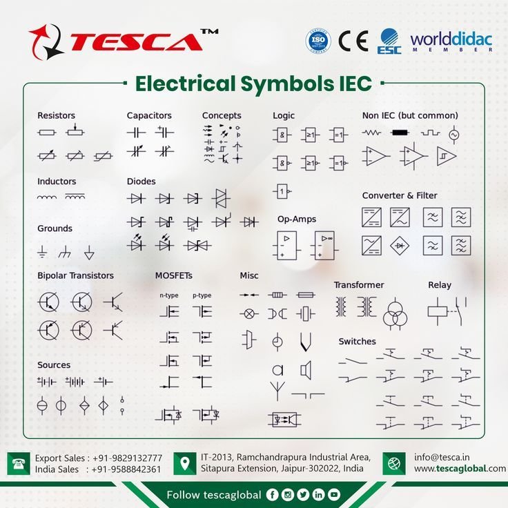
- Resistors: These components reduce current flow and drop voltage, dissipating energy as heat.
- You'll typically see zig-zag lines (IEEE standard) or rectangular blocks (IEC standard) representing a fixed resistor.
- Adjustable Resistors (Potentiometers/Rheostats): Often have an arrow pointing to the main resistance element, indicating variable resistance. Trimmer resistors are a smaller, preset version, adjusted during manufacturing or calibration.
- Specialized Resistors: Keep an eye out for thermistors (resistance changes with temperature) and photoresistors (LDRs, resistance changes with light intensity), both having unique properties indicated by their specific symbols.
- Capacitors: These components store electrical charge and are crucial for filtering, timing, and energy storage. They act as short circuits for AC and open circuits for DC over different timeframes.
- Symbols typically depict two parallel lines, sometimes one curved for polarized capacitors (requiring specific orientation). Adjustable capacitors will have an arrow through them, allowing their capacitance value to be varied.
- Inductors / Coils: Inductors, coils, or solenoids generate a magnetic field when current flows, finding use in filters, chokes, and transformers. They oppose changes in current.
- Represented by a series of loops or coils. An iron core inductor will show lines adjacent to the coils, indicating a ferromagnetic core, while a variable inductor will have an arrow passing through it, signifying adjustable inductance.
To get a much deeper dive into how these fundamental components operate and how their symbols translate to their physical counterparts, make sure to Explore electronic components. Understand circuit symbols..
Activating Circuits: Switches, Relays, and Power Sources
Interactivity and power are at the heart of many electrical designs. Understanding the symbols for switches, relays, and power sources is key to controlling circuits, turning them on or off, and supplying the necessary energy.
- Switch Symbols: These components mechanically disconnect or connect current pathways.
- Basic Switch: An open gap in a line, often with a pivoted arm, indicating an open circuit until closed.
- Pushbutton Switch (N.O./N.C.): Momentary switches that activate only while pressed. Normally open (N.O.) means current flows when pressed; normally closed (N.C.) means current stops when pressed.
- DIP Switch: Multiple small switches grouped for onboard configuration, typically found on circuit boards.
- Relays: These use an electromagnet to open or close connections, allowing a small current in a control circuit to operate a larger current in a separate circuit. The symbol typically shows a coil and a set of contacts.
- Jumper & Solder Bridge: Simple, often temporary, ways to close a connection manually on a PCB. A jumper involves inserting a conductive block, while a solder bridge is formed by applying solder across two points.
- Power Supply Symbols: Indicate where the circuit gets its energy, defining the source of voltage or current.
- DC Voltage Source: Parallel lines, one longer (positive) and one shorter (negative), representing direct current.
- AC Voltage Source: A circle with a sine wave inside, representing alternating current, often generated by mechanical rotation.
- Other symbols denote constant current sources or voltage/current dependent sources, which are more complex power generation mechanisms.
For systems that involve significant power distribution and control mechanisms, understanding these symbols in context is paramount. We cover these in more detail when discussing Common power and motor symbols.
The Semiconductor Revolution: Diodes and Transistors
Semiconductors are the backbone of modern electronics, enabling logic, amplification, and efficient power control. Their symbols are critical to interpreting complex digital and analog circuits that form the core of almost all electronic devices.
- Diodes: These components fundamentally allow current flow in one direction only (from anode to cathode), acting as a one-way valve for electricity. The basic symbol is an arrow pointing to a line.
- Zener Diode: Designed to allow current in reverse when a specific breakdown voltage is reached, often used for voltage regulation.
- Schottky Diode: Known for low forward voltage drop and fast switching speeds.
- LED (Light Emitting Diode): A diode symbol with two arrows pointing away, clearly indicating its function of emitting light when current flows.
- Photodiode: A diode symbol with two arrows pointing towards it, indicating its function of detecting light and allowing current flow when exposed.
- Transistors: The foundational building blocks of amplifiers, electronic switches, and microprocessors, capable of controlling large currents with small input signals.
- Bipolar Junction Transistors (BJTs): NPN and PNP types, identified by an arrow on the emitter indicating current direction and polarity.
- Field-Effect Transistors (FETs): N-channel and P-channel types, including MOSFETs, which have different gate structures and offer high input impedance. Darlington transistors combine two BJTs for higher current gain.
Understanding the nuances of these semiconductor symbols is fundamental to designing and troubleshooting advanced electronic systems.
Logic and Processing: Gates, Flip-Flops, and Converters
In the realm of digital electronics, logic gates perform fundamental operations, and more complex symbols represent data storage and conversion, forming the intelligence behind computers and control systems.
- Logic Gates: These are the basic decision-making units of digital circuits, performing Boolean operations on binary inputs.
- NOT Gate (Inverter): A triangle with a circle at the output, meaning it outputs the opposite of its input.
- AND Gate: Outputs 1 (high) only if all inputs are 1.
- OR Gate: Outputs 1 if any input is 1.
- NAND / NOR / XOR Gates: Combinations of basic gates with inverted outputs or exclusive logic, each with unique decision-making properties.
- D Flip-Flop: A symbol for a device that stores one bit of data, acting as a basic memory element crucial in registers and sequential logic.
- Multiplexer (MUX) & Demultiplexer (DEMUX): Symbols for components that route data. A MUX connects multiple inputs to a single output line based on a selector, while a DEMUX does the opposite, connecting a single input to one of many outputs.
- Analog-to-Digital Converter (ADC) & Digital-to-Analog Converter (DAC): Essential for interfacing between the analog world (like sensors) and the digital world (like microcontrollers), and vice versa.
Delving into these symbols is crucial for anyone working with digital systems. For a detailed exploration of how these components form the intelligence of modern devices, you'll want to explore the Digital Logic & Control System pillar.
Measuring, Indicating, and Protecting Circuits
Beyond core components, circuits often include devices for monitoring performance, providing feedback to users, and ensuring safety through protection mechanisms. These symbols are vital for comprehensive circuit understanding.
- Meter Symbols: Used to represent measurement devices, typically circles with a letter inside.
- Voltmeter (V): Measures voltage, always connected in parallel across the component.
- Ammeter (A): Measures current, always connected in series within the circuit path.
- Ohmmeter (Ω): Measures resistance of a component (usually when power is off).
- Wattmeter (W): Measures electrical power.
- Lamps / Light Bulbs: Simple circles with an 'X' or coil inside, indicating light emission when current flows through them.
- Buzzers & Electric Bells: Symbols representing auditory indicators that produce sounds when activated.
- Fuses: A critical safety device, often a wavy line or rectangle, designed to disconnect a circuit when current exceeds a safe threshold, protecting other components from damage.
- Transformers: Used to change AC voltage levels from high to low or low to high through electromagnetic induction, typically shown as two coils separated by lines (representing an iron core).
- Electric Motor: A circle with an 'M' inside, representing a device that converts electrical energy into mechanical motion.
Bringing It All Together: Interpreting Full Schematics
Understanding individual symbols is the first step; the true power comes from interpreting how they interact within a complete circuit diagram. A schematic tells a story – the flow of energy, the transformation of signals, and the logic of operation. By recognizing patterns and component relationships, you can troubleshoot issues, modify designs, and even create your own circuits from scratch.
This skill is invaluable for hobbyists and professionals alike, enabling you to move beyond basic component identification to a holistic understanding of electronic systems. To truly master the art of reading and understanding circuit layouts, we highly recommend our guide on Understanding and Interpreting Electrical Schematics. This resource will help you connect the dots between individual symbols and the complete functional diagram, preparing you for real-world applications.
Beyond the Basics: Specialized Symbols and Integrated Functions
The world of electrical engineering is vast, and so are its symbols. As circuits become more complex and integrated, you'll encounter many specialized symbols that represent more complex or integrated functions.
- Bus: A thick line often representing multiple wires carrying data or address lines in parallel, streamlining diagrams.
- Optocoupler: A component that optically isolates two parts of a circuit, preventing electrical interference while still allowing signal transfer.
- Speaker & Microphone: Symbols for converting electrical signals to sound waves and vice versa, representing transducers.
- Amplifier: A triangle pointing in the direction of signal flow, indicating signal gain and strengthening.
- Schmitt Trigger: A symbol representing a comparator with hysteresis, useful for noise reduction in digital inputs.
- Crystal Oscillator: Used to generate precise frequency clock signals, essential for timing in digital systems.
- Antenna Symbols: Various designs indicating devices for transmitting and receiving radio waves, fundamental to wireless communication.
These symbols often represent entire functional blocks within a larger design, making schematics more concise and readable, especially for complex integrated circuits and systems.
Your Journey Continues: Mastering the Language of Circuits
Navigating the diagram of electrical symbols is a foundational skill for anyone interested in electronics, from casual enthusiasts to seasoned engineers. Each symbol is a tiny piece of a larger puzzle, and by understanding their meanings, you gain the ability to comprehend, communicate, and innovate in the world of electricity. This hub has laid out the essential categories, providing a gateway to deeper understanding.
Keep exploring, keep building, and remember that every circuit has a story to tell, waiting for you to decipher its language. The more you practice reading schematics, the more intuitive these symbols will become, opening up a world of possibilities for design, repair, and creation in the fascinating field of electronics.