Ever stared at an electronics schematic, feeling like you'd stumbled upon an alien language? You're not alone. What looks like a jumble of lines, shapes, and squiggles is actually the incredibly precise visual language engineers use to design everything from your smartphone to industrial robots. At the heart of this language, especially in the digital realm, are Digital Logic & Control System Symbols. Mastering them isn't just about memorizing shapes; it's about understanding the fundamental behaviors that power our connected world.
This guide will demystify these symbols, transforming complex diagrams into clear stories about how electricity flows, data processes, and machines respond. By the time you're done, you'll not only read a schematic with confidence but also understand the ingenious logic behind it.
At a Glance: Your Schematic Superpowers Await
- Decipher the "Logic": Learn the core symbols for digital gates (AND, OR, NOT, etc.) – the building blocks of all digital decisions.
- Understand Memory: Grasp how flip-flops and registers store and manipulate data, bit by bit.
- Navigate Data Flow: See how multiplexers, demultiplexers, encoders, and decoders direct information through a circuit.
- Bridge Analog & Digital: Discover the symbols for Analog-to-Digital (ADC) and Digital-to-Analog (DAC) converters, the crucial translators between physical and digital worlds.
- Recognize Timing & Control: Identify oscillators, clocks, and other control elements that synchronize a system.
- Interpret Key Components: Familiarize yourself with common components like LEDs, relays, and displays, understanding their roles at a glance.
- Build Confidence: Gain practical tips for reading complex schematics and even sketching your own.
The Unspoken Language of Electronics: Why Symbols Matter
Imagine trying to build a house without architectural blueprints, or conducting an orchestra without sheet music. Impossible, right? Electronics schematics serve the same vital purpose. They are the universal language, a shorthand that transcends spoken languages and even specific hardware implementations. When you see an AND gate symbol, whether it's implemented with discrete transistors, within an integrated circuit (IC), or even as a software function, you instantly know its logical behavior.
Understanding these Digital Logic & Control System Symbols isn't merely academic; it's profoundly practical. It empowers you to:
- Troubleshoot Circuits: Pinpoint where a signal might be dropping, a logic operation is failing, or a component isn't behaving as expected.
- Design Your Own Projects: Sketch out your ideas for automation, data processing, or interactive systems with clarity and precision.
- Communicate Effectively: Collaborate with other engineers, technicians, or hobbyists, ensuring everyone is on the same page.
- Reverse Engineer: Understand how existing devices work by tracing their internal logic.
It's about gaining literacy in a language that defines the technological world around us. Let's start breaking down the vocabulary.
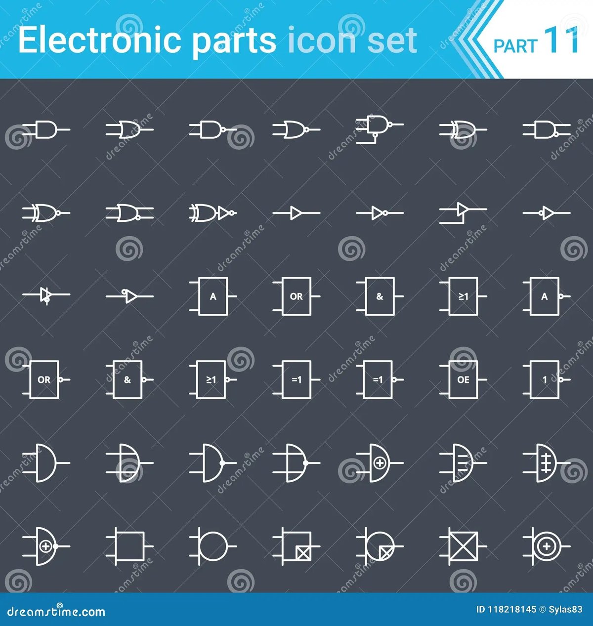
Decoding the Digital DNA: Logic Gates Explained
At the very foundation of digital electronics lie logic gates. These aren't just abstract concepts; they're tiny electronic circuits that take one or more binary inputs (0 or 1, low or high voltage) and produce a single binary output based on a specific logical rule. They are the decision-makers of the digital world, forming the logic that controls everything from simple alarms to complex microprocessors. If you want to understand what a logic gate fundamentally does, recognizing its symbol is the first step.
The Core Building Blocks: AND, OR, NOT (Inverter)
These three gates are the absolute basics. Master them, and you've got a strong foundation.
- AND Gate:
- Symbol: D-shaped, with two or more inputs entering the flat side and one output leaving the curved side.
- Function: It's like a multi-way switch. The output is HIGH (1) only if all its inputs are HIGH (1). If even one input is LOW (0), the output is LOW.
- Analogy: You get dessert (output HIGH) only if you finish your vegetables (input A HIGH) AND your homework (input B HIGH).
- OR Gate:
- Symbol: A curved input side that flares out, narrowing to a single output. Looks a bit like a rocket ship or a shield.
- Function: The output is HIGH (1) if at least one of its inputs is HIGH (1). It only outputs LOW (0) if all its inputs are LOW (0).
- Analogy: You can go to the park (output HIGH) if it's sunny (input A HIGH) OR if your friend is going (input B HIGH).
- NOT Gate (Inverter):
- Symbol: A triangle pointing to the right, with a small circle (bubble) at its output. The bubble signifies inversion.
- Function: It simply flips the input. If the input is HIGH (1), the output is LOW (0). If the input is LOW (0), the output is HIGH (1).
- Analogy: It's like a light switch where "on" means "off" and "off" means "on."
Advanced Operations: NAND, NOR, XOR, XNOR
These gates are derived from the basic three but are incredibly common in their own right, often simpler to implement in hardware.
- NAND Gate:
- Symbol: Identical to an AND gate, but with a small circle (bubble) at its output.
- Function: Short for "NOT AND." The output is LOW (0) only when all inputs are HIGH (1). Otherwise, the output is HIGH. It's the opposite of an AND gate.
- NOR Gate:
- Symbol: Identical to an OR gate, but with a small circle (bubble) at its output.
- Function: Short for "NOT OR." The output is HIGH (1) only when all inputs are LOW (0). Otherwise, the output is LOW. It's the opposite of an OR gate.
- XOR Gate (Exclusive OR):
- Symbol: Similar to an OR gate, but with an additional curved line at the input side.
- Function: Outputs HIGH (1) only when its inputs are different. If both inputs are the same (both HIGH or both LOW), the output is LOW (0).
- Use Case: Often used for parity checking, encryption, and simple comparison logic.
- XNOR Gate (Exclusive NOR):
- Symbol: Identical to an XOR gate, but with a small circle (bubble) at its output.
- Function: Outputs HIGH (1) only when its inputs are the same. If inputs are different, the output is LOW (0). It's the opposite of an XOR gate.
- Use Case: Useful for determining if two bits are identical.
Signal Strengthening: The Buffer
- Symbol: A simple triangle pointing to the right, without the bubble at the output.
- Function: A buffer does no logical operation. Its output is always the same as its input. Its purpose is to strengthen a signal, allowing it to drive more components or travel longer distances without degradation. Think of it as an electronic booster shot.
Remembering the Bit: Flip-Flops and Memory Elements
While logic gates make decisions, flip-flops remember them. These are the fundamental memory elements in digital circuits, capable of storing a single bit of information (a 0 or a 1) and holding it until instructed otherwise. They are the building blocks for registers, counters, and all forms of digital memory. If you want to delve deeper into flip-flops, understanding these symbols is key.
Basic Bit Storage: SR Flip-Flop
- Symbol: A rectangular block, often labeled "SR," with inputs 'S' (Set) and 'R' (Reset), and outputs 'Q' and 'Q-bar' (the inverse of Q).
- Function: The simplest flip-flop. 'S' sets the output Q to 1, and 'R' resets Q to 0. It "remembers" its last state until a new 'Set' or 'Reset' signal arrives. A common issue is the "forbidden state" where both S and R are active simultaneously.
Data Integrity: D Flip-Flop
- Symbol: A rectangular block labeled "D," with an input 'D' (Data), a 'Clock' input (often denoted by a triangle or small arrow), and outputs 'Q' and 'Q-bar'.
- Function: The "Delay" or "Data" flip-flop. It stores the value present at its 'D' input only when triggered by a clock edge (either rising or falling, indicated by the clock symbol). This makes it very predictable and widely used for synchronous data storage.
Universal Toggles: JK & T Flip-Flops
These are more versatile variations, building on the basic flip-flop concept.
- JK Flip-Flop:
- Symbol: A rectangular block labeled "JK," with inputs 'J' and 'K', a 'Clock' input, and outputs 'Q' and 'Q-bar'.
- Function: A "universal" flip-flop because it can behave like an SR flip-flop, a D flip-flop, or a T flip-flop, depending on how its J and K inputs are used. Its unique feature is the "toggle" state: when both J and K are HIGH, the output Q toggles (flips) its state with each clock pulse.
- T Flip-Flop:
- Symbol: A rectangular block labeled "T," with an input 'T' (Toggle), a 'Clock' input, and outputs 'Q' and 'Q-bar'.
- Function: A "Toggle" flip-flop. When its 'T' input is HIGH, the output Q toggles its state (from 0 to 1, or 1 to 0) with every clock pulse. When 'T' is LOW, it holds its current state. Useful for counters and frequency division.
Routing Data Traffic: Multiplexers and Demultiplexers
Think of these components as digital traffic controllers. They manage the flow of data, directing it from one path to many or many to one, based on control signals.
Directing Inputs: The Mux (Multiplexer)
- Symbol: A trapezoidal shape, wider on the input side and narrower on the output side, with select lines entering from the side. Often labeled "MUX" or "DMUX" with the number of inputs (e.g., "4:1 MUX").
- Function: A multiplexer selects one of several input lines and forwards it to a single output line. The selection is controlled by a set of "select" inputs.
- Analogy: A TV channel selector. You have many channels (inputs), but you choose only one to view (output) using the remote (select lines).
Splitting Outputs: The Demux (Demultiplexer)
- Symbol: A trapezoidal shape, narrower on the input side and wider on the output side, with select lines entering from the side. Often labeled "DMUX" or "1:4 DEMUX."
- Function: A demultiplexer takes a single input line and routes it to one of many output lines. Again, the specific output is chosen by the "select" inputs.
- Analogy: A mail sorter. A single mailbag (input) is directed to one specific mailbox (output) based on the address (select lines).
Translating Information: Encoders and Decoders
These components are about converting data from one format to another, often to condense or expand information.
Compacting Data: Encoders
- Symbol: A rectangular block often labeled "Encoder" or "Pri-Enc" (Priority Encoder), with multiple input lines on one side and fewer output lines on the other.
- Function: An encoder converts multiple input lines into a smaller set of outputs, usually in a binary or BCD (Binary-Coded Decimal) format. For example, a 10-line to 4-line encoder might take a single active input from 0-9 and output its 4-bit binary equivalent.
- Common Application: Reading keyboard presses. When you press 'A', an encoder converts that physical press into a unique binary code.
Expanding Outputs: Decoders
- Symbol: A rectangular block often labeled "Decoder," with fewer input lines on one side and multiple output lines on the other.
- Function: A decoder performs the reverse operation of an encoder. It converts a binary input into a single active output line. For example, a 2-to-4 line decoder might take a 2-bit binary input (00, 01, 10, 11) and activate one of four output lines.
- Common Application: Display drivers. A 7-segment display decoder takes a 4-bit binary input representing a digit (0-9) and activates the correct segments on the display to show that digit.
Storing Sequences and Parallel Data: Registers
Registers are essentially groups of flip-flops connected together, designed to store multiple bits of data (a "word" or "byte") and often to perform simple operations on them, like shifting data.
Serializing Data: Shift Registers
- Symbol: A long rectangular block, often with multiple stages indicated internally, and specific inputs/outputs for serial data in/out (SDI/SDO) and parallel data in/out (PDI/PDO), plus a clock and control lines (e.g., Shift/Load, Left/Right).
- Function: A shift register moves stored data bit by bit, either to the left or right, with each clock pulse. This is crucial for converting serial data (one bit at a time) to parallel data (many bits simultaneously), and vice-versa, or for creating delays.
- Example: Sending data over a single wire (serial) and then converting it to a parallel format to drive a set of LEDs.
Instant Access: Parallel Registers
- Symbol: A rectangular block, typically with multiple parallel input lines and multiple parallel output lines, plus a clock input and potentially an enable/load control.
- Function: A parallel register stores multiple bits of data simultaneously and outputs them in parallel. All bits are written or read at the same time, making it faster for block data transfers compared to serial.
- Use Case: Holding the state of a microprocessor's internal calculations or temporarily storing data before it's processed further.
Making Decisions: Comparators
Comparators are straightforward in their purpose: they evaluate two inputs and generate an output based on their relationship.
The Digital Referee: How Comparators Work
- Symbol: Often a rectangular block labeled "Comp" or "Comparator," with two inputs (A and B) and typically three outputs: A>B, A<B, and A=B.
- Function: A digital comparator compares two binary numbers (or single bits) and outputs a signal indicating whether one is greater than, less than, or equal to the other.
- Example: In a control system, a comparator might check if a sensor's temperature reading (Input A) has exceeded a critical threshold (Input B), triggering an alarm if A > B.
Visualizing Data: Digital Display Components
For humans to interact with digital systems, we need ways to see the data. Display components are the visual interfaces.
Numeric Readouts: 7-Segment Displays
- Symbol: A stylized rectangle with seven individual segments (typically represented as lines) arranged in a figure-eight pattern. Each segment usually has its own input line.
- Function: Displays decimal numbers (0-9) by illuminating specific combinations of its seven segments. Often found in older digital clocks, calculators, and simple readouts.
Alphanumeric Versatility: 14-Segment & 16-Segment Displays
- Symbol: Similar to the 7-segment but with more segments to allow for displaying letters and a wider range of symbols. They might resemble a rectangle with intersecting lines inside.
- Function: These displays offer more segment flexibility than 7-segment displays, enabling the representation of alphanumeric characters (A-Z, 0-9) and some special symbols.
Flexible Graphics: Dot Matrix Displays
- Symbol: A grid of dots (representing individual LEDs) arranged in a rectangular pattern (e.g., 5x7, 8x8).
- Function: These displays provide the most flexibility for displaying text, custom characters, and even simple graphics, as each individual dot (pixel) can be controlled. Common in moving message signs, older printer displays, and some instrument panels.
Bridging Worlds: Analog-to-Digital (ADC) & Digital-to-Analog (DAC) Converters
Most of the real world—temperature, sound, light, pressure—is analog, meaning it varies continuously. Digital systems, however, only understand discrete 0s and 1s. ADCs and DACs are the essential translators that bridge these two domains. For understanding ADCs and DACs is crucial for any system interacting with the physical world.
From Real World to Binary: ADCs (Analog-to-Digital Converters)
- Symbol: A rectangular block labeled "ADC," with an analog input line (often marked "Ain" or "V_in") and multiple digital output lines (often parallel).
- Function: An ADC takes a continuous analog voltage or current signal and converts it into a digital binary number that a microcontroller or other digital system can understand and process.
- Example: A temperature sensor outputs a varying analog voltage. An ADC converts this voltage into a binary number that a thermostat's digital logic can interpret.
From Binary to Real World: DACs (Digital-to-Analog Converters)
- Symbol: A rectangular block labeled "DAC," with multiple digital input lines and a single analog output line (often marked "Aout" or "V_out").
- Function: A DAC performs the reverse of an ADC. It takes a digital binary number and converts it back into a corresponding analog voltage or current.
- Example: A digital audio player stores music as binary data. A DAC converts this data into an analog audio signal that can drive headphones or speakers.
Setting the Pace: Oscillators and Clocks
Digital systems are often synchronous, meaning all operations are timed and coordinated by a central clock signal. Oscillators and clock generators provide this crucial heartbeat.
Precision Timing: Crystal Oscillators
- Symbol: A rectangular block labeled "XTAL" or "OSC," often with two pins, and sometimes with a separate ground connection or internal circuitry. The component itself might be represented by a jagged line between two dots.
- Function: Crystal oscillators generate extremely precise and stable periodic electrical signals (clock pulses) using the piezoelectric properties of a vibrating crystal (usually quartz). They are vital for microcontrollers, CPUs, and any application requiring accurate timing.
Synchronizing Operations: Clock Signal Generators
- Symbol: A simple square wave or sine wave symbol often enclosed in a circle or box, sometimes labeled "CLK."
- Function: More generally, a clock signal generator produces the periodic timing signals that synchronize operations across a digital circuit. While crystal oscillators are a type of clock generator, this symbol is used for any source of a clock signal, which might be internal to an IC or derived from another source. It's the conductor keeping the entire digital orchestra in time.
The Brain's Notebooks: Memory Components
Digital systems need places to store both the instructions they follow and the data they process. Memory components are fundamental for this.
Active Workspace: RAM (Random Access Memory)
- Symbol: Typically a rectangular block labeled "RAM" or "SRAM" (Static RAM) or "DRAM" (Dynamic RAM), with data input/output lines, address lines, and control lines (e.g., Read/Write Enable).
- Function: RAM is temporary, volatile memory used for actively storing data and instructions that the CPU is currently using. It's "random access" because any memory location can be accessed directly in roughly the same amount of time. When the power goes off, RAM forgets everything.
- Analogy: RAM is like your desk while you're working – lots of space for current tasks, but you clear it at the end of the day.
Permanent Instructions: ROM (Read-Only Memory)
- Symbol: A rectangular block labeled "ROM" or "EEPROM" (Electrically Erasable Programmable ROM) or "Flash," with address lines and data output lines.
- Function: ROM is non-volatile memory that permanently stores firmware, boot-up instructions, or data that does not need to change frequently. It retains its contents even when power is off.
- Analogy: ROM is like a printed instruction manual – it's there even if the lights go out, and you can't easily change it.
Essential Support Players: Miscellaneous Components
Not every component fits neatly into a logic or memory category, but many are crucial for the overall functionality and interaction of a digital system. These "miscellaneous" components provide feedback, isolation, and control.
Indicators & Feedback: LEDs, Buzzers
- LED (Light Emitting Diode):
- Symbol: A standard diode symbol (triangle pointing right into a line) with two arrows pointing away from it, indicating light emission.
- Function: Emits light when current flows through it in the correct direction. Used as visual indicators, backlights, or in displays.
- Buzzer:
- Symbol: Often a circle with a jagged line inside, or a small box with specific terminal markings.
- Function: Produces an audible sound when an electrical signal is applied. Used for alerts, alarms, or auditory feedback.
Isolation & Control: Optocouplers, Relays
- Optocoupler (Opto-isolator):
- Symbol: Combines an LED symbol on the input side with a phototransistor or photo-diode symbol on the output side, enclosed in a dashed box to show optical coupling and electrical isolation.
- Function: Transfers electrical signals between two entirely isolated circuits using light. This is critical for safety, protecting sensitive low-voltage circuits from high-voltage sections, and reducing electrical noise.
- Relay:
- Symbol: Often two parts: a coil symbol (a rectangle or a series of loops) and a switch symbol (which can be normally open (NO) or normally closed (NC)), often enclosed in a dashed box.
- Function: An electrically operated switch. A small current through the coil creates a magnetic field that closes or opens a separate set of contacts, allowing a low-power control circuit to switch a high-power load.
Visual Output: LCDs (Liquid Crystal Displays)
- Symbol: A rectangular block often labeled "LCD," with numerous input/output pins for data, control signals, and power.
- Function: Displays information using liquid crystals, which change their light-transmitting properties when an electrical field is applied. Common in calculators, digital watches, and small screens in embedded systems.
Putting It All Together: Reading and Designing Schematics
Now that you're familiar with the key Digital Logic & Control System Symbols, let's talk about how to apply this knowledge. Reading a schematic is like reading a story; you start at the beginning (power input) and follow the narrative of signal flow. When you reading circuit diagrams, keep these pointers in mind.
Tips for Deciphering a Schematic
- Start with the Power: Locate the power supply symbols (VCC, GND, VDD, VSS). These tell you where the energy comes from.
- Follow the Clock: Identify the clock signal. In synchronous digital circuits, the clock dictates the timing of operations. It's often the heartbeat of the system.
- Trace the Inputs: Find where signals enter the circuit (buttons, sensors, data lines). How do they connect to the first logic gates or flip-flops?
- Understand the Flow: Signals generally flow from left to right, or top to bottom. Pay attention to arrows indicating direction.
- Deconstruct Complex Blocks: If you see a large IC, try to understand its overall function first (e.g., a microcontroller, a memory chip, a specialized driver). Many chips contain multiple logic gates or flip-flops internally. For instance, to explore the basics of microcontrollers, you'll see how many of these symbols represent functions within that single chip.
- Look for Inversion Bubbles: Remember the small circles (bubbles) on gate outputs or flip-flop inputs. They mean "NOT" or "active low." This is a common source of confusion if overlooked.
- Identify Buses: Multiple parallel lines grouped together, often with a bold line and a number (e.g., "/8" for an 8-bit bus), represent data pathways.
- Context is Key: Some symbols can be slightly different depending on the standard (IEEE, ANSI, IEC). If unsure, consult a reference or the component's datasheet. For a general overview of electrical symbols diagram, it can provide a broader context.
Best Practices for Drawing Your Own
- Be Consistent: Use a single standard for all your symbols.
- Keep it Neat: Good spacing, straight lines, and clear labeling make your schematic easy to read.
- Label Everything: All components should have a unique designator (e.g., U1 for ICs, R1 for resistors) and a value or description.
- Use Net Names: For long connections, or connections that cross pages, use "net names" (e.g., "DATA_BUS_0", "CLK_IN") to clarify connections without drawing convoluted lines.
- Show Power and Ground Clearly: Always denote power and ground connections.
- Add Explanatory Notes: If a section of your circuit is particularly complex or has a specific function, add a text note to clarify.
Common Pitfalls to Avoid
- Misinterpreting Active Low: Forgetting that a bubble means an "active low" signal can lead to incorrect logic.
- Ignoring the Clock: Many digital circuits are synchronous. Failing to account for clock signals and setup/hold times for memory elements can cause erratic behavior.
- Overlooking Power Connections: Even logic gates need power and ground. Missing these connections on a schematic is a common error, especially for large ICs.
- Poor Grounding: Digital noise can be a big issue. While schematics show logical connections, proper physical grounding practices are crucial for real-world circuit stability.
Your Next Steps in the Digital World
You've just navigated the essential language of Digital Logic & Control System Symbols. This journey from basic gates to complex memory and conversion units is more than just an academic exercise; it's a practical skill that unlocks countless possibilities in electronics. You now have the foundational knowledge to look at a circuit diagram not as a cryptic puzzle, but as a clear blueprint of functional behavior.
The real learning begins now. Grab a datasheet for a common digital IC (like a 74HC00 NAND gate or a 74HC74 D flip-flop) and try to identify the pins corresponding to the inputs, outputs, power, and clock. Better yet, find a simple schematic for a project like a digital counter or a simple alarm circuit and try to trace the signal path using the symbols you've learned.
The digital world is built on these foundational symbols. By understanding them, you're not just reading diagrams; you're starting to speak the language of innovation itself. Keep exploring, keep building, and keep demystifying the incredible logic that powers our modern existence.