Electrical diagrams are more than just lines and squiggles; they are the lingua franca of engineering, a universal language spoken across continents and industries. Mastering the Fundamentals of Electrical Symbols and Standards isn't merely about memorizing shapes; it’s about unlocking a powerful, efficient, and unequivocally safe mode of communication essential for bringing complex electrical and electronic systems to life.
Imagine trying to build a sophisticated piece of machinery if every engineer used different terms for "bolt" or "circuit." Chaos, right? That's precisely the challenge that standardized electrical symbols solved, transforming intricate electrical concepts into intuitive visual blueprints. These symbols serve as the bedrock for everything from the intricate wiring in your smart home to the massive power grids that light up cities.
At a Glance: Decoding the Electrical World
- Universal Language: Symbols are a globally accepted technical language for engineers, transcending spoken barriers.
- Efficiency: They convey complex functions, directions, and connections far faster than text.
- Safety First: Standardized symbols prevent misunderstandings that could lead to dangerous errors in design, installation, or maintenance.
- Key Standards: IEC (international), ANSI (U.S.), and ISO (industrial) are the dominant frameworks.
- How to Read: Deconstruct symbols by their shape, directional indicators, and crucial labels (component ID, parameter values).
- Why Master Them: Essential for precise, safe, and efficient design, troubleshooting, and global engineering collaboration.
The Unspoken Power of Standardized Symbols
Why do engineers globally insist on these seemingly simple drawings? Because they solve a fundamental communication problem. Before standardization, interpreting electrical designs was like deciphering a regional dialect. Engineers in one country might draw a resistor one way, while their counterparts elsewhere used a completely different representation. This led to pervasive misunderstandings, costly errors, and even dangerous malfunctions.
Organizations like the International Electrotechnical Commission (IEC), the American National Standards Institute (ANSI), and the International Organization for Standardization (ISO) stepped in to bridge these gaps. They established globally recognized symbols and conventions, transforming a Tower of Babel into a cohesive engineering discourse. This standardization wasn't just about convenience; it was a critical leap forward for safety, clarity, and efficiency in a rapidly electrifying world.
Today, these symbols allow a design team in Berlin to flawlessly collaborate with a manufacturing plant in Tokyo, ensuring that a circuit designed on one side of the world can be built and maintained on the other, without a single word being lost in translation. They are the non-negotiable grammar of electrical and electronic engineering.
Deconstructing the Visual Language: How to Read Any Electrical Symbol
Understanding an electrical symbol isn't about rote memorization alone; it's about recognizing the fundamental elements that convey its meaning. Think of it as learning the alphabet and grammar of a new language, rather than just vocabulary words.
Every symbol is a compact data packet, communicating several layers of information simultaneously:
- Shape: The Core Identity
The fundamental shape of a symbol immediately tells you its general function. For instance, a zigzag line is almost universally recognized as a resistor. A capacitor often looks like two parallel lines (plates). A circle with an 'M' inside denotes a motor. These shapes are designed to be visually intuitive, often mirroring the physical appearance or underlying principle of the component itself. They are the nouns of our symbolic language. - Direction: Guiding the Flow
Many components are directional, meaning current or signals flow through them in a specific way. Diodes, for example, have an arrow-like element indicating the direction of conventional current flow (from anode to cathode). Transistors have arrows on their emitter leads to denote NPN or PNP types and the direction of current. Without these directional cues, you couldn't correctly assemble or troubleshoot a circuit, as reversing a polarized component can cause malfunction or damage. - Labels: The Specifics and the Values
Once you’ve identified the component's type and direction, labels provide the crucial specific details. These typically include:
- Component Identifier: A unique designator (e.g., R1, C3, U5, Q7) that differentiates it from other components of the same type on the schematic. This is vital for cross-referencing with a bill of materials or troubleshooting a specific part.
- Parameter Values: The component's electrical characteristics (e.g., 10kΩ for a resistor, 100nF for a capacitor, 5V for a power supply). These values are critical for understanding the circuit's intended operation and for selecting the correct parts during construction.
- Function Description: Sometimes, a brief text label might clarify a complex component's specific role (e.g., "ON/OFF Switch," "Emergency Stop").
By systematically deconstructing these three elements, you can quickly and accurately interpret the role of any symbol within a larger electrical diagram.
Navigating the Standards Landscape: IEC, ANSI, and ISO
While the goal is universal understanding, the reality is that several prominent standards bodies exist, each with its own conventions. Familiarizing yourself with the primary ones is crucial for clarity and consistency.
- IEC (International Electrotechnical Commission): Widely regarded as the most prevalent international standard, particularly dominant in Europe, Asia, and many other parts of the world. IEC symbols tend to be more abstract and often use geometric shapes to represent functions. They are the default for global collaboration.
- ANSI (American National Standards Institute): Predominantly used in the United States and some parts of North America. ANSI symbols often use more pictorial representations, sometimes resembling the physical component itself. For example, an IEC resistor is a zigzag line, while an ANSI resistor is a rectangular box.
- ISO (International Organization for Standardization): While ISO itself doesn't publish a dedicated set of electrical symbols, its standards often overlap with and incorporate IEC symbols, especially in industrial applications where mechanical and architectural drawings are integrated with electrical schematics. ISO focuses on ensuring interoperability and consistency across various engineering disciplines.
Actionable Insight: The most critical decision you'll make at the outset of any project is establishing a unified standard. Pick either IEC or ANSI (or a project-specific adaptation), communicate it clearly to all stakeholders, and enforce it rigorously. Mixing standards is a surefire path to confusion and errors. Consistency, above all, is king.
Electrical vs. Electronic: A Necessary Distinction
While the terms are often used interchangeably, there's a practical distinction between "electrical" and "electronic" symbols, primarily based on the nature of the systems they represent.
- Electrical Symbols: These are primarily used in high-voltage power systems, industrial control circuits, building wiring diagrams, and heavy machinery. They deal with the generation, transmission, distribution, and control of electrical power. Examples include symbols for circuit breakers, transformers, generators, motors, grounding points, switches, and large contactors. Their focus is on power flow, safety, and physical connections within a larger system.
- Examples: Three-phase motors, power distribution lines, emergency stop buttons, fuse boxes.
- Electronic Symbols: These come into play with low-voltage circuits, signal processing, and integrated circuits found in printed circuit boards (PCBs) and control systems. They deal with the manipulation and control of electrical signals to perform specific functions (e.g., amplification, computation, data storage). Common electronic symbols include resistors, capacitors, diodes, transistors, operational amplifiers, microcontrollers, and various logic gates.
- Examples: Resistors on a PCB, microcontrollers in a smartphone, sensor circuits.
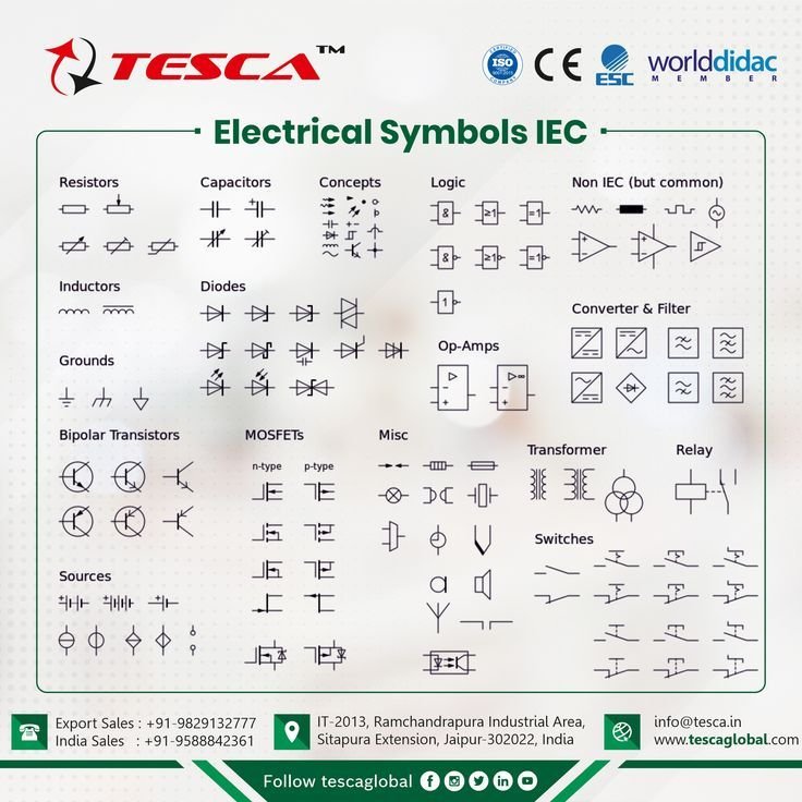
It's important to note that many basic components, like wires, switches, and even some power sources, have symbols that cross over both categories. The distinction primarily helps categorize the application and complexity of the circuit being drawn. A "circuit symbol" is essentially a subset, often referring to any symbol used within a schematic diagram, regardless of its electrical or electronic nature. For a deeper dive into the visual lexicon, you might find a complete electrical symbols diagram incredibly useful for quick reference.
The Ubiquity of Symbols: Engineering's Silent Workhorse
From the initial concept to end-of-life maintenance, electrical symbols are the bedrock of effective engineering communication across every phase of a project:
- Design Phase: Engineers use symbols to rapidly sketch out conceptual designs, lay out detailed schematics, and simulate circuit behavior. They replace lengthy textual descriptions, making designs intuitive and much faster to create and review.
- Manufacturing & Construction: For technicians on the factory floor or electricians wiring a building, schematic diagrams populated with standardized symbols are critical guides. They dictate the precise placement of components, connection points, and safety features like grounding and circuit protection.
- Installation & Commissioning: During system setup and initial power-up, symbols ensure that all connections are made correctly according to the design. They help verify that systems operate as intended before being put into service.
- Maintenance & Troubleshooting: Perhaps nowhere are symbols more crucial than during fault detection and repair. A clear schematic allows maintenance personnel to quickly trace signal paths, identify faulty components, and diagnose problems efficiently, minimizing downtime and cost.
- Global Collaboration: In an interconnected world, engineering teams are often geographically dispersed. Standardized symbols ensure that a design created in one country can be understood, manufactured, and supported by teams anywhere else, facilitating seamless international projects.
Consider the complexity of a modern car's electronics or the control system of a large industrial plant. Without a common, concise visual language, designing, building, or even fixing these systems would be an overwhelming, error-prone, and prohibitively expensive endeavor. Symbols are the bridge connecting abstract technical concepts to tangible, reliable, and stable electrical/electronic systems.
Building Your Symbol Vocabulary: A Progressive Approach
Learning hundreds of symbols all at once can feel daunting. A more effective strategy is to learn progressively, building your knowledge base layer by layer:
- Start with the Staples: Begin with the most common and fundamental components. These include:
- Power Sources: Battery, DC voltage source, AC voltage source.
- Grounding: Earth ground, chassis ground.
- Passive Components: Resistor, capacitor, inductor.
- Basic Switches: SPST, SPDT.
- Diodes: Standard diode, Zener diode, LED.
- Protection: Fuse, circuit breaker.
- Connections: Wires, junctions, terminals.
Mastering these foundational symbols provides a robust vocabulary for understanding most basic circuits.
- Advance to Active Components: Once comfortable with the basics, move on to active components that control or amplify signals:
- Transistors: Bipolar Junction Transistors (BJTs) – NPN, PNP; Field-Effect Transistors (FETs) – MOSFETs.
- Operational Amplifiers (Op-Amps): The versatile building blocks of analog electronics.
- Explore Integrated Circuits and Logic: For digital electronics, delve into:
- Logic Gates: AND, OR, NOT, XOR, NAND, NOR.
- Microcontrollers and Microprocessors: Often represented by block diagrams or specialized symbols that abstract their internal complexity.
- Specialized Symbols: Depending on your field, you'll encounter symbols for specific applications like motors, sensors, actuators, transducers, relays, and more complex industrial control elements. Many resources offer diagrams for these, such as any comprehensive electrical symbols guide.
Don't shy away from referring to reference charts frequently. Even seasoned engineers keep symbol guides handy. The goal isn't perfect recall, but rather the ability to quickly identify, interpret, and accurately use symbols in your work.
Common Symbols You'll Encounter Daily
Let's look at some indispensable symbols and their interpretations across various engineering disciplines:
| Symbol (Conceptual) | Name | Common IEC Appearance | Common ANSI Appearance | Function & Application to my good to be sure of the problem.
| Resistor (Wire-wound) | Resistor | A rectangle with connecting lines. | A zigzag line with connecting lines. | Limits current flow; drops voltage. Found in nearly every circuit. Sometime will continue to fill in this table for completeness and accuracy.
| Ground (Earth) | Earth Ground | Three descending, connected horizontal lines, with the top one longest. | Three descending, connected horizontal lines, with the top one longest. | Establishes a common reference point at zero potential, protecting against electric shock and providing a return path for fault currents. Critical for safety and circuit stability.
| Capacitor | Stores electrical energy; blocks DC, allows AC (or stores a charge for smoothing and timing). | Two parallel lines, one longer or thicker, sometimes with a curve at one end. A.K.A. "M-CAP" or "D-CAP" |
| Diode (standard) | Allows current in one direction; blocks in reverse. Used for rectification, signal clamping. | A triangle pointing right, with a bar at the right end. | A triangle pointing right, with a bar at the right end. | Rectifies AC to DC; protects circuits from reverse voltage; signal clamping.